|
Don’t you hate it when you’re cooking something and, despite the thermostat being set low, your steak (or whatever else it is that you’re cooking) chars to a nice crunchy black. It’s bad enough if you have burnt dinner but if you are actually trying to control the temperature for a chemical or physical heating process then over-temperature can have significant (and sometimes nasty) repercussions including unintended ignition or destruction of the thing you are heating. Further, if you are heating a volatile combustible then arcing at the thermostat contacts risks a potential explosion.
Hence this project.
Warnings
- This project runs on mains voltages. Any constructor should ensure sound wiring techniques and fuse protection for mains operated equipment in accordance with jurisdictional regulations and prudent safety requirements.
- Over current and thermal fuse protection are essential components for this design.
- Hot plates are designed to get hot. This means they are capable of causing burn injuries and potentially starting a fire. It is recommended that a hot plate should be monitored while in use. It also means that wiring in close proximity to the element must be appropriately rated for high temperature operation.
- Some aspects of this design are specific to a 1,500 W resistive load and operation from 230 V AC mains. For alternative specifications refer to the cited literature.
- This design is provided free and comes without any implied warranty or statement of fitness for purpose. All I ask is that you acknowledge your source should you use or build on it.
Quite some years back when servicing of electric hot plates/stirrers for a university I routinely replaced the electromechanical thermostats with open loop electronic proportional controllers using an RCA CA3059 Zero Voltage Switch (ZVS) and an LM 3900 Norton quad Operational Amplifier configured as a triangle wave generator. RCA application note ICAN-6182 describes the general design of proportional temperature controllers. These simple low cost electronic units provided improved temperature control over the thermostats and eliminated the risk of thermostat arc ignition. A further benefit was that the ZVS eliminates mains switching noise.
I have had a few enquires about the RCA application note and have scanned the original document in PDF format. Given that the CA3059 is no longer in production, the publication is over 30 years old, and the application note is less than 10% of the text I have scanned and published it with the RCA copyright notice for study only. Note that this is a large file (28 MB) due to the small size of the original font. Click on the link below to view the document.
As an aside, the primary reason for hot plate damage was inadvertent overheating resulting in boil-over and consequent corrosion damage to the heating element and the thermostat. While my colleague and I probably serviced at least one hot plate every month we did not see a single proportionally controlled device returned for service in the five years I worked there!
Unfortunately the CA3059 is no longer readily available but there are equivalent devices, including Atmel’s T2117 which has everything that the CA3059 had and an internal ramp generator to boot.
My specific requirements are to control a low cost mains powered hot plate to within +/- 2.5°C of set temperature over the range of 50 to 250°C. Under-temperature is tolerable, particularly when changing the thermal load (putting a pot of cold water on the element) but over temperature is unacceptable.
Starting Material
I have a 1,500 W Cascade electric hot plate (Figure 1). It was cheap. It is controlled by a closed loop electromechanical thermostat loosely thermally coupled to the heating element (Figure 2). The thermostat is typical of what you might find in a clothing iron with bimetallic strip for temperature sensing, a pre-tensioning screw for temperature control, and a secondary bistable spring for positive contact switching.
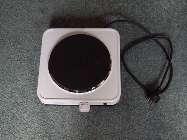
Figure 1. A Low Cost Hot Plate
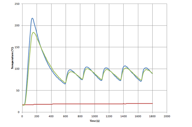
Figure 2. The Thermostat
I set about measuring the hot plate’s heating characteristics. I let a beaker of oil come to thermal equilibrium at a mid-range thermostat setting and measured its temperature over time (Figure 3).
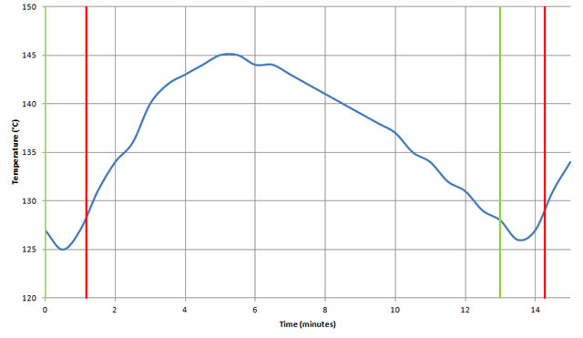
Figure 3. Steady State Performance of Hot Plate
There are a few things to notice from the graph. The green and red vertical lines show the times when the element switches on and off. You can see that the thermal lag between the heating element and the top of the hot plate is about 30 seconds and the thermal inertia of the plate is almost 2 minutes. The rate of initial heating and final cooling are approximately 6° and -4 °C/min respectively.
As a further experiment I measured the initial response of the hot plate from cold, turning the control up until the thermostat came on and measuring the temperature of the oil over time (Figure 4).
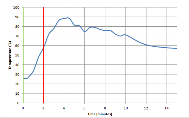
Figure 4. Initial Response of Hot Plate
This second graph shows a significant 65°C overshoot during initial heating. The rate of temperature rise during initial heating is almost 20°C/min while the rate of initial cooling after 10 minutes is about -2.7°C/min. These are the respective maximum heating and minimum cooling rates for this hot plate.
Temperature Sensor
For closed loop control we need a measure of the temperature of the hot plate.
- Semiconductor devices are out because they can’t handle the upper temperature limit.
- A platinum resistance thermometer is very linear over the intended temperature range but as you might expect, these are expensive and not particularly robust.
- Thermocouples are good for high temperature, relatively linear over the temperatures of interest (+/- 3°C for a K Type), have a short time constant, permit ready temperature display, are robust and low cost. However they require reference junction compensation (the hot plate case gets quite warm) and the output is a relatively low 40 uV/K around 25°C.
- Thermistors are robust, have a short time constant and low cost, but they are highly non-linear, somewhat less robust than thermocouples and have a limited maximum temperature (typically 250°C).
In the interests of simplicity, low cost and small size I have decided to use a thermistor sensor and dispense with a display of actual hot plate temperature. I have found a range of Negative Temperature Coefficient (NTC) thermistors rated for 300°C with a time constant of about 7 seconds that should be up to the task.
The first mission is to linearize the thermistor output. While this is a classic microprocessor application I’ve decided to stick with an analogue electronic approach for now. The resistance temperature characteristic of my particular thermistor is shown in Figure 5. By selecting appropriate series and parallel resistors we can optimize a nearly linear voltage response over the temperature range of interest.
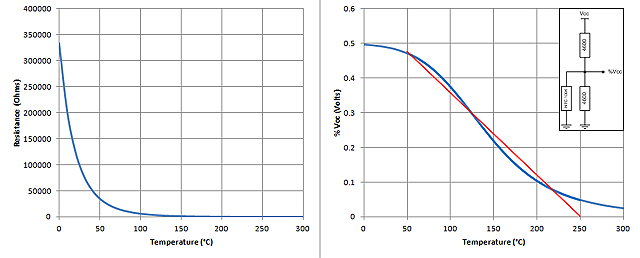
Figure 5. Near-Linear Response from NTC Thermistor
Graphs 3, 4 and 5 provide sufficient information for establishing a closed loop proportional controller design. The initial overshoot dictates that we start to proportionally reduce power to the element about 30°C below the set point. Any less and we can anticipate overshoot. The power control cycle needs to be long compared with the mains frequency and short compared with the thermal lag. A ramp cycle time of about 3 seconds should be a good compromise.
I have made a thermal model of the existing hot plate by accounting for the lag time, thermal inertia and simultaneous cooling using simple linear relationships at 30 second intervals. This thermal model can also be applied to the proposed proportional controller to predict its performance. The set temperature was 125°C. The results are shown in Figure 6. For such a crude model the cyclic behaviour of the thermostat (red line) compares quite closely with the actual performance shown in Figure 3. Note also the 30 s thermal lag at the beginning of the heating cycle. The model could be significantly improved by making the heating and cooling rates non-linear and dependent on the hot plate temperature. The model would then predict a significant increase in initial temperature rise as shown in Figure 4.
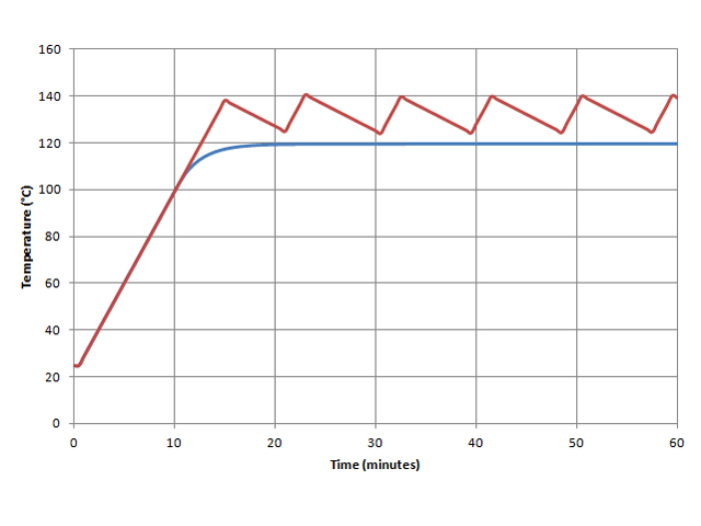
Figure 6. Modelled Performance
(Red: Thermostat, Blue: Proportional Controller)
The circuit diagram for my proposed proportional controller is shown in Figure 7. The outputs of the lineariized thermistor and control potentiometer are filtered and then buffered by LM324 operational amplifiers, as any change in resistive load will alter their response. The control potentiometer has two series resistors to allow for hardware programming of voltage span (set temperature). The two op amp buffers are followed by a differential amplifier with a gain of 77 so that the 6 Volt amplitude of the T2117 saw tooth generator corresponds with a 30°C temperature difference between the set voltage and the linearized thermistor output. The unused op amp could be used to drive an LED, but at additional current consumption and increased component cost.
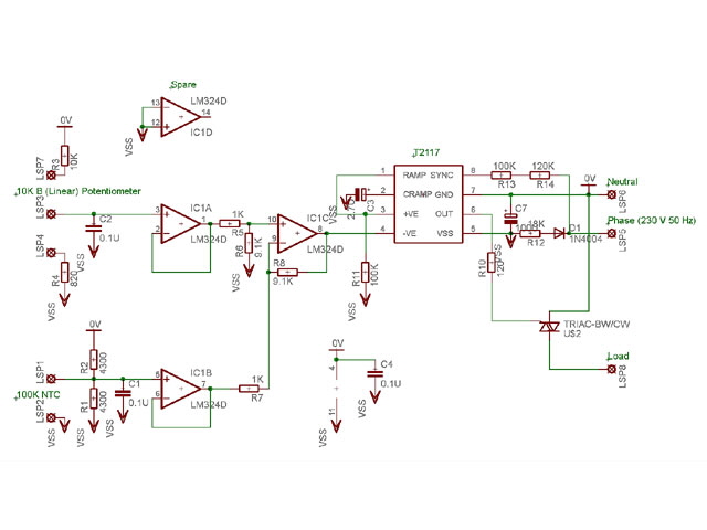
Figure 7. Proportional Controller
Details of the selection of other components can be obtained directly from the T2117 data sheet application notes. Note that the 18K Ohm 2 W power supply resistor selection is highly dependent on mains voltage and any additional current requirements on board. Your triac must be appropriately rated for the intended load and this will dictate the required gate current (triggering in quadrants II and III). Make sure that the triac hold current will be exceeded by the load within the gate drive time, particularly for high resistive loads such as a few hundred Watts of light bulbs.
You will see that I have used two resistors (R13 and 14) from phase to the zero crossing detector input at pin 8 of the T2117. This is to ensure adequate physical separation of the low voltage circuitry from mains phase.
The printed circuit board layout is shown in Figure 8. It is a single sided board to minimize construction cost. Note the width of the tracks handling load current, the track separation to minimize the risk of over-voltage breakdown, and the two isolated 3 mm diameter mounting holes (the hot plate case is grounded and it is not good form to connect neutral to ground except at the switchboard). As a further safety precaution I have selected an isolated tab triac. You might choose to do the same.
The PCB design also allows implementation of an open loop proportional controller by omitting six passive components and incorporating two wire bridges. However a specifically designed open loop controller board will reduce the board area by 1/3 and remove the need for the LM 324 as well.

Figure 8. Printed Circuit Board Layout
(Top Image ~ Actual Size: 70 mm x 25 mm, 2.8” x 1”)
I was hoping to have made the board yesterday but my ammonium persulphate etching solution is well and truly expired and I can’t concoct a replacement, short of nitric acid. Actually this is not strictly true but it will take longer and be more expensive to make a copper (II) chloride etch than to purchase 400 g of ammonium persulphate from a local supplier. Construction and testing will therefore take a few more days.
14 February and the board is made and assembled as shown in Figure 9. As an added precaution I have used lead free high temperature solder. There are just eight wiring connections to make: Phase, Neutral, Load, two for the thermistor, and three for the control potentiometer. Testing should be completed tomorrow followed by assembly in the hot plate. The board will mount on two insulating stand-offs, one of which also secures the triac.
I intend using as much of the existing glass fibre insulated cable as possible. The only challenges should be mounting and wiring of the thermistor. While my welder is still under development it is quite capable of welding the thermistor leads now so I will probably attempt this. However let’s cross these bridges when we come to them.
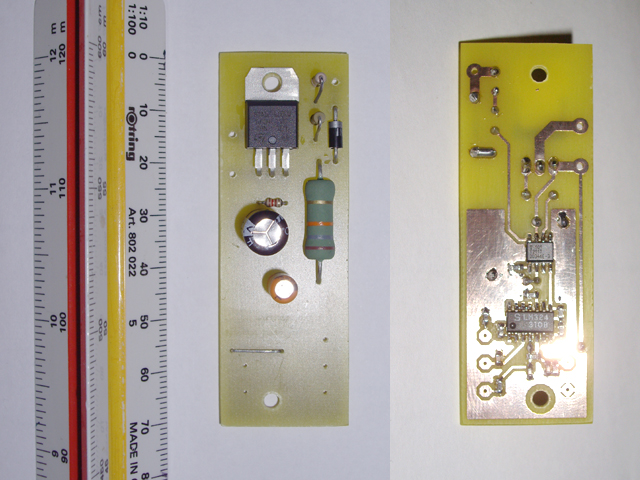
Figure 9. Controller Board Assembled
Having disassembled the hot plate I have contemplated options for mounting the thermistor. The most readily accessible mounting point is an existing 16 mm deep M4 threaded hole in the centre of the hot plate that was used for mounting the thermostat. I figure that if I can get the thermistor in good thermal contact with the bottom of this hole then I will reduce the thermal lag and get a reasonable measurement of the surface temperature of the hot plate. First up I need some ceramic or fibreglass insulators so I’ll be going shopping tomorrow. While I’d like to cement the thermistor in place this will make servicing or replacement difficult. I intend putting thermal paste in the bottom third of the hole, inserting the thermistor and its insulating material and then packing it in position with ceramic fibre. The thermistor’s flying leads (NiFe) will go to a ceramic terminal block that will be positioned to hold everything in place.
On further disassembly of the hot plate I found an even better thermistor mounting hole right beside the heating element. The following five images (10 a though e) show the thermistor (yes, it’s tiny) and the mounting sequence. For the record I put some tin oxide thermal paste in the hole, then inserted the thermistor with the ceramic insulator, then pressed a 20 mm length of glass fibre braid as a packing gland. I checked the resistance at each stage of the process to ensure that the thermistor leads were not shorted and were isolated from the case. As an aside an open circuit thermistor will turn the element full on until the thermal fuse blows. A thermistor short circuit between leads or to the case should turn the element off and should not result in electrical failure of the controller.
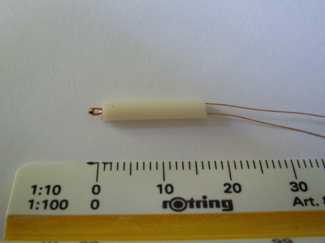
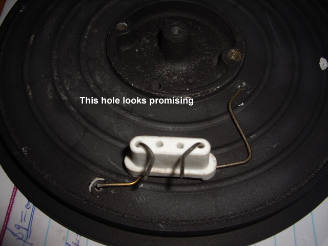
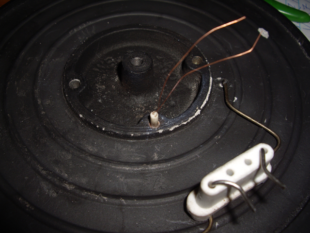
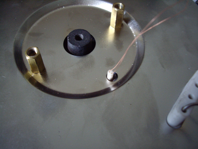
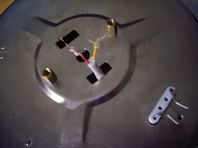
Figures 10 a to e. Mounting the Thermistor
Here are a few construction notes for you.
- Trying to cut ceramic rod with steel tools is a waste of time and effort and will quickly dull the sharp edge of your tools. You can either grind to length using a high speed diamond cutting wheel or score with a diamond glass cutter and fracture over a sharp edge. The last method worked well for me.
- I have used braided fibreglass sleeves for electrical insulation (good to around 600°C). When you cut this stuff it instantly starts to unravel at the ends. Immediately after cutting to length fuse the ends with a butane torch flame. They will shrink a bit but they won’t unravel so easily.
- Handling fibreglass means gloves, minimal uncovered skin and eye protection as a minimum. A particulate face mask is also a good idea. That itching feeling you may have experienced on your arms and around your nose after handling fibreglass is due to fibres penetrating your skin. You don’t want this.
17 February and the controller components were mounted in the top of the case (see Figure 11), wired up and put on the test bench. There was only one construction issue when I attempted to use my welder to make connections to the element. I used weld schedules developed some time ago and literally vaporized the leads. Oops! Thankfully there was enough remaining to allow a screw block connection.
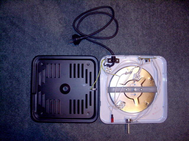
Figure 11. Assembly
Everything has been working well over four hours of testing. The results from temperature Set Point 2 with 1 litre of water from cold and Set Point 3 with 200 ml of oil, both from cold are shown in Figure 12. This should be compared to Figures 3, 4 and 6 above.
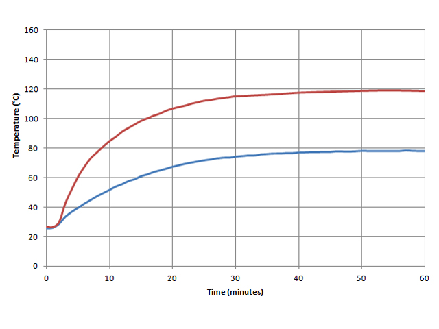
Figure 12. Heating Tests
There is a nice initial dead-band on the control where everything is off (about 1/8 th of a turn). As anticipated there is no overshoot and the final temperatures are stable to within +/- 0.5°C. The set point control appears to be approximately linear with a measured upper temperature limit of 187°C. This can be readily increased by replacing a resistor.
On the other side of the ledger the location of the thermistor has significantly reduced the lag compared with the bimetallic thermostat resulting in excessive time to come up to temperature. Reducing the gain of the differential amplifier will help a bit but really I need more thermal inertia. I suspect that I’ll be moving the thermistor back from the element to the threaded hole in the centre of the hot plate. The thermal path from the heating element to the original thermostat bimetallic strip was at least 85 mm, while for the thermistor it is somewhat less than 20 mm. If I aim for the middle of the element then this will be somewhat less than half of the original thermal path length.
When the hot plate comes to equilibrium the heating cycle is oscillating with a frequency of just over 120 seconds. Further, time in the proportional band is limited to about 30 seconds. This tells me that the rate of temperature decrease and increase is too high. I have a few minor changes to make and I’ll be doing some more analysis before making these.
In order to increase the rise time and provide improved proportional control I have moved the thermistor back to the centre of the hot plate (into the M4 threaded hole) and reduced the gain of the differential amplifier to 10. R6 and R8 in the schematic at Figure 7 are now 9.1 K Ohm. The modified performance is shown in Figure 13.
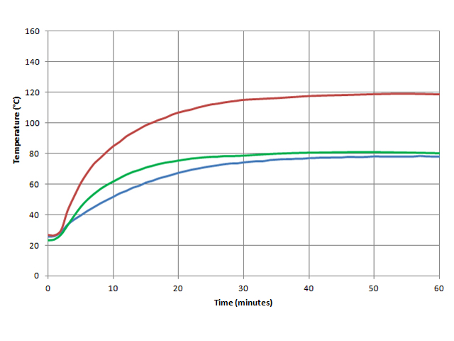
Figure 13. Improved Rise Time
While I could make the rise time faster this will change the temperature regulation with load. At the moment the temperature difference with a change in load is negligible (less than 1°C difference between a beaker with 200 ml of water and a pot with 2 litres of water).
Here is a summary of measured performance (the results of six tests, each more than an hour in duration, over a range of temperatures).
- Rise Time: Better than 20 minutes to 90% and 30 minutes to 95% of final temperature from ambient.
- Proportional Ramp Time: 2.9 seconds
- Linearity: +/- 5%.
- Maximum Temperature: 187°C.
- Accuracy: +/- 0.5°C across range.
- Overshoot: None.
- Non-arcing design for reduced explosion potential.
Not bad for a $NZ25 hot plate and half as much again in components. An equivalent performance laboratory hot plate cost around ten times this. If you add the reduced explosion potential inherent in this design then you won’t be getting much change from $1000.
This project is now complete. Please contact me with any questions, comments of suggestions.
|